English
  cn
cn
When selecting a small fluid control component, the part number alone does not always tell an engineer whether the component will fit a specific tubing arrangement. Tube ID is important, but the physical dimensions of the plug also determine how much installation space is required and how the component relates to the surrounding tubing or assembly.
This is particularly relevant when working with Plugs PG95-220, a PP plug designed for tubing with a 9.5 mm tube ID. Its dimensions are defined by several parameters, including L, X and C. Understanding what these dimensions represent in a product drawing or selection table makes it easier to compare the plug with other sizes in the same series and avoid selecting a part based only on nominal tube diameter.
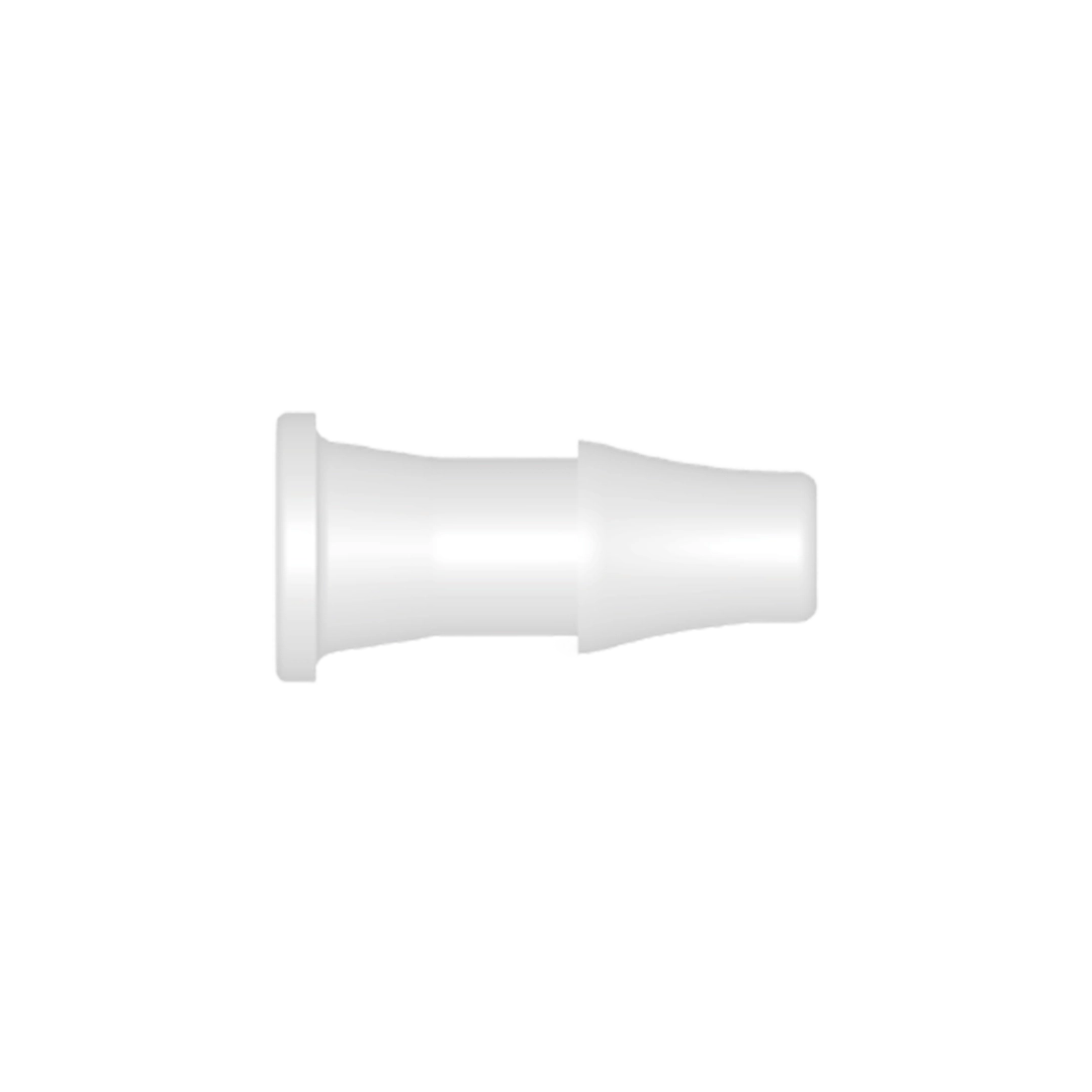
Why L, X and C Dimensions Matter
A plug can match the nominal tube ID and still be unsuitable for a particular assembly if its overall geometry is not considered.
For engineers and procurement teams, dimensional information normally answers several practical questions. How much space does the plug occupy? How large is the section around the tube opening? How does the plug compare with a smaller model? Is there enough clearance for installation and removal?
The L, X and C values provide a compact way to describe these physical characteristics.
For PG95-220, the Product Selection data lists a 9.5 mm Tube ID, PP material and Natural color, with L at 24.6 mm, X at 11.7 mm and C at 13.0 mm. These values should be considered together rather than evaluated independently.
The purpose of a dimensional table is not simply to provide numbers. It allows the selected component to be checked against the actual mechanical space available in the fluid control assembly.
Understanding the L Dimension
L is one of the key dimensions to check when determining the physical length of a plug.
For the PG series, L changes progressively as the compatible tube ID increases. The listed values are 6.0 mm for PG16-061, 8.5 mm for PG24-086, 10.5 mm for PG32-106, 13.0 mm for PG40-130, 16.0 mm for PG48-160, 20.0 mm for PG64-200 and 24.6 mm for PG95-220.
This progression is useful when comparing models within the same product family.
PG95-220 is designed for the largest tube ID in this listed series, so its L dimension is also the largest among these seven models. If an assembly has limited axial space, the engineer should therefore check the available clearance rather than assuming that all PG plugs occupy approximately the same space.
In practical terms, L is particularly useful during layout planning. A component that fits the tube opening may still require additional space around the tubing path. Checking the dimensional drawing before ordering can prevent interference with nearby components, brackets or enclosure surfaces.
What the X Dimension Tells You
The X dimension provides another reference for understanding the plug's geometry.
In the PG series, X increases from 2.4 mm on PG16-061 to 11.7 mm on PG95-220. The intermediate models provide a gradual range of dimensions corresponding to different tube IDs.
This makes X useful when comparing plugs that appear similar in function but differ substantially in size.
For a 9.5 mm tube application, selecting PG95-220 rather than a smaller PG model is not simply a matter of choosing the largest available number. The engineer should confirm that the corresponding X dimension is compatible with the mechanical arrangement around the tubing.
This becomes more important in compact instrumentation, where several fluid lines may run close together. Even a small dimensional difference can affect spacing between neighboring components.
How the C Dimension Supports Component Selection
The C dimension is another important part of the plug geometry. For PG95-220, the listed C value is 13.0 mm.
Looking across the series, C increases from 3.0 mm on PG16-061 through 4.5 mm, 6.0 mm, 7.5 mm, 9.0 mm and 12.0 mm before reaching 13.0 mm on PG95-220.
The gradual change gives engineers a useful reference when selecting a plug based on tube size and surrounding space.
Rather than checking only the 9.5 mm Tube ID, it is better to review the complete dimensional set. A tube may accept the plug functionally, but the external geometry still needs to fit the actual assembly.
This is especially relevant for equipment with defined component spacing. Medical devices, analytical instruments, laboratory systems and environmental equipment often contain multiple tubing paths and compact fluid-control assemblies. Dimensional compatibility can therefore be just as important as nominal tubing compatibility.
PG95-220 Compared With Smaller PG Models
The PG series makes it possible to see how the dimensions change as the tube ID increases.
| P/N | Tube ID | L | X | C |
|---|---|---|---|---|
| PG16-061 | 1.6 mm | 6.0 mm | 2.4 mm | 3.0 mm |
| PG24-086 | 2.4 mm | 8.5 mm | 3.6 mm | 4.5 mm |
| PG32-106 | 3.2 mm | 10.5 mm | 4.8 mm | 6.0 mm |
| PG40-130 | 4.0 mm | 13.0 mm | 6.0 mm | 7.5 mm |
| PG48-160 | 4.8 mm | 16.0 mm | 7.2 mm | 9.0 mm |
| PG64-200 | 6.4 mm | 20.0 mm | 9.6 mm | 12.0 mm |
| PG95-220 | 9.5 mm | 24.6 mm | 11.7 mm | 13.0 mm |
This comparison shows why model selection should be based on the complete dimensional specification. The PG95-220 is not simply a larger version of the same physical component. Its geometry changes with the larger compatible tube ID.
For procurement teams, the table also provides a quick way to identify whether an alternative PG model is actually suitable for a particular tubing size.
PP Material and Installation Considerations
The dimensional specification is only one part of the selection process. PG95-220 uses PP, or polypropylene, and is listed in Natural color.
The material choice is relevant when the plug is being integrated into a fluid control system because the component needs to be considered together with the tubing, fluid environment and surrounding materials.
The product is also described with features including high precision, simple installation and reliable performance. These characteristics are particularly useful when a plug is used as part of a repeatable assembly process.
However, installation should still be based on the actual mechanical design. The tube ID should be confirmed first, followed by the plug dimensions and the available installation space. Material compatibility and the operating requirements of the complete system should then be verified.
A Practical Way to Check PG95-220 Before Ordering
A straightforward selection process can reduce dimensional mistakes.
First, confirm the tubing's internal diameter. For PG95-220, the specified Tube ID is 9.5 mm.
Next, check the dimensional requirements of the assembly. The listed L, X and C values for PG95-220 are 24.6 mm, 11.7 mm and 13.0 mm respectively in the Product Selection data.
Then consider the installation environment. If the plug will be installed close to another component, the surrounding clearance should be checked against the complete geometry rather than only the tube opening.
Finally, verify the material requirement. PG95-220 is manufactured from PP and is listed in Natural color.
This process is simple, but it is more reliable than selecting a part number based only on a similar-looking component or nominal tube size.
Where Dimensional Consistency Becomes Important
Dimensional consistency matters most when plugs are used across repeated equipment designs.
For example, an equipment manufacturer may use several tubing sizes within one fluid circuit. A standardized product family makes it easier to select corresponding plugs while keeping the basic product structure consistent.
The PG series covers tube IDs from 1.6 mm to 9.5 mm. This range allows engineers to compare models using the same basic selection logic: tube ID first, followed by L, X, C, material and installation requirements.
For larger assemblies, this approach can also simplify purchasing and documentation. Instead of treating every plug as a completely separate component, engineering teams can establish a consistent dimensional selection process across the series.
AIIBOOM's Approach to Precision Fluid Components
AIIBOOM develops and manufactures precision fluid control components and customized solutions for medical devices, life sciences, diagnostics, analytical instrumentation and environmental applications.
The company operates R&D centers in Shenzhen, China, and Sendai, Japan, with the two teams focusing on technology development and process optimization. Its manufacturing operations cover 20,000 m² across facilities in Dongguan, Guangdong, and Tongling, Anhui, China.
AIIBOOM states that its production and quality systems are supported by ISO 9001 and ISO 14001 certified management systems. The company also reports more than 20 years of industry experience, over 1,000 partners and more than 20 patent certificates.
For precision fluid-control components, these capabilities are relevant because product selection often involves more than identifying a nominal tube size. Dimensional consistency, manufacturing control and application requirements all affect how a small component performs within a larger system.
Using the Dimensions as a Selection Tool
The value of PG95-220 is not defined by its part number alone. The 9.5 mm Tube ID identifies its intended tubing size, while the L, X and C dimensions describe the physical geometry that must be considered during integration.
For the listed PG95-220 data, L is 24.6 mm, X is 11.7 mm and C is 13.0 mm. Comparing these dimensions with the smaller PG models shows how component geometry changes across the series.
For engineers and buyers, the practical approach is straightforward: confirm the tube ID, review all three dimensional parameters, check the available installation space, and verify material compatibility before finalizing the component.
By treating L, X and C as part of the selection process rather than as isolated numbers on a specification sheet, Plugs PG95-220 can be evaluated more accurately for precision tubing and fluid-control assemblies.